These are the following steps to design 2 bit synchronous up down counter using T flip flop:
Step 1: To design a synchronous up-down counter, we need one extra input called control input. Other than this, in next state column, half of the input must be appeared as up counter and the remaining must be treated as a down counter.
Step 2: After that, we need to construct a state table with excitation table.
Note: To construct excitation table from state table you should know the excitation table of respective flip flop, in this case, it is T flip flop. So check the excitation table for T flip flop Which is:
T Flip Flop Excitation Table
| Present state | Next State | T |
|---|---|---|
| 0 | 0 | 0 |
| 0 | 1 | 1 |
| 1 | 0 | 1 |
| 1 | 1 | 0 |
So, the above table is the excitation table for T Flip Flop.
State Table with excitation table
| Control input | Present State | Next State | Flip Flop | |||
|---|---|---|---|---|---|---|
| Ci | Q2 | Q1 | Q'2 | Q'1 | T2 | T1 |
| 0 | 0 | 0 | 0 | 1 | 0 | 1 |
| 0 | 0 | 1 | 1 | 0 | 1 | 1 |
| 0 | 1 | 0 | 1 | 1 | 0 | 1 |
| 0 | 1 | 1 | 0 | 0 | 1 | 1 |
| 1 | 0 | 0 | 1 | 1 | 1 | 1 |
| 1 | 0 | 1 | 0 | 0 | 0 | 1 |
| 1 | 1 | 0 | 0 | 1 | 1 | 1 |
| 1 | 1 | 1 | 1 | 0 | 0 | 1 |
Above the table is created as per follow :
When Q2 =0 which is the present state and Q2‘=0 which is next state then T2 become 0 [As per excitation table, have a look ]
Similarly, if Q2 is 0 and Q2‘ is 1 then T2 becomes 1.
In a similar way, it goes on .
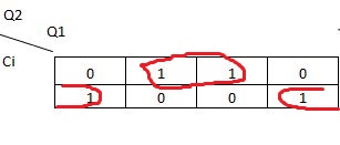
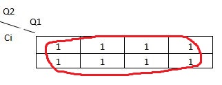
Step 3: After making the excitation table the next thing to do is dig out the equation from the boolean algebra or K map for the design of the counter. So, for T1 and T2we got 1, and Q1‘.Ci + Q1.Ci’
K-Map
For T2 Flip flop,
For T1 Flip flop,
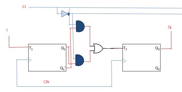
Step 4: Lastly according to the equation got from K map create the design for 2 bit synchronous up down counter.
Related posts:
Design a 2 bit Synchronous down counter using T Flip flop?
Design a 2 bit Synchronous up counter using T Flip flop?
