Decoder is also a Combinational circuit which transforms given inputs to a maximum number of outputs (maximum outputs equal to 2n and n are given inputs ).
In other words, a decoder can be defined as a logic circuit that receives binary input and produces output corresponding to that very binary input.
A block diagram of decoder consists of n input lines, one or more enable inputs and 2n maximum number of output lines.
To construct a decoder, we require to know the number of all possible output lines that totally depends on the given input.
So, if n represents given input lines then possible output lines would be 2n.
Decoder with three inputs would give 8 outputs (n=2,23 that is 8).
In this article, we’ll be going to design 3 to 8 decoder step by step.
Here are the steps to Construct 3 to 8 Decoder
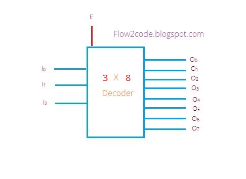
Step 1. Now we know possible outputs for 3 inputs, so construct 3 to 8 decoder, having 3 input lines, a enable input and 8 output lines.
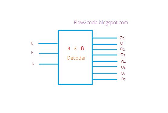
In the below diagram, given input represented as I2, I1 and I0 , all possible outputs named as O0, O1, O2,O3, O4, O5,O6 & O7 and a E were represented by Enable input.
With Enable input
Without Enable input
Step 2. Now, it turns to construct the truth table for 3 to 8 decoder. E input can be considered as a control input.
Mean to say, If E equals to 0 then the decoder would be considered as disabled regardless of what inputs are, If E equals to 1 then the decoder would work as per inputs.
Truth table without E input
| Inputs | Outputs | |||||||||
|---|---|---|---|---|---|---|---|---|---|---|
| I2 | I1 | I0 | O7 | O6 | O5 | O4 | O3 | O2 | O1 | O0 |
| 0 | 0 | 0 | 0 | 0 | 0 | 0 | 0 | 0 | 0 | 1 |
| 0 | 0 | 1 | 0 | 0 | 0 | 0 | 0 | 0 | 1 | 0 |
| 0 | 1 | 0 | 0 | 0 | 0 | 0 | 0 | 1 | 0 | 0 |
| 0 | 1 | 1 | 0 | 0 | 0 | 0 | 1 | 0 | 0 | 0 |
| 1 | 0 | 0 | 0 | 0 | 0 | 1 | 0 | 0 | 0 | 0 |
| 1 | 0 | 1 | 0 | 0 | 1 | 0 | 0 | 0 | 0 | 0 |
| 1 | 1 | 0 | 0 | 1 | 0 | 0 | 0 | 0 | 0 | 0 |
| 1 | 1 | 1 | 1 | 0 | 0 | 0 | 0 | 0 | 0 | 0 |
We can represent the following output as:
O0 = I0‘.I1‘.I2‘
O1 = I0.I1‘.I2‘
O3 = I0.I1.I2‘
O4 = I0‘.I1‘.I2
O5 = I0.I1‘.I2
O6 = I0‘.I1.I2
O7 = I0.I1.I2
Truth table with E input
| Inputs | |||||||||||
|---|---|---|---|---|---|---|---|---|---|---|---|
| E | I2 | I1 | I0 | O7 | O6 | O5 | O4 | O3 | O2 | O1 | O0 |
| 0 | - | - | - | 0 | 0 | 0 | 0 | 0 | 0 | 0 | 0 |
| 1 | 0 | 0 | 0 | 0 | 0 | 0 | 0 | 0 | 0 | 0 | 1 |
| 1 | 0 | 0 | 1 | 0 | 0 | 0 | 0 | 0 | 0 | 1 | 0 |
| 1 | 0 | 1 | 0 | 0 | 0 | 0 | 0 | 0 | 1 | 0 | 0 |
| 1 | 0 | 1 | 1 | 0 | 0 | 0 | 0 | 1 | 0 | 0 | 0 |
| 1 | 1 | 0 | 0 | 0 | 0 | 0 | 1 | 0 | 0 | 0 | 0 |
| 1 | 1 | 0 | 1 | 0 | 0 | 1 | 0 | 0 | 0 | 0 | 0 |
| 1 | 1 | 1 | 0 | 0 | 1 | 0 | 0 | 0 | 0 | 0 | 0 |
| 1 | 1 | 1 | 1 | 1 | 0 | 0 | 0 | 0 | 0 | 0 | 0 |
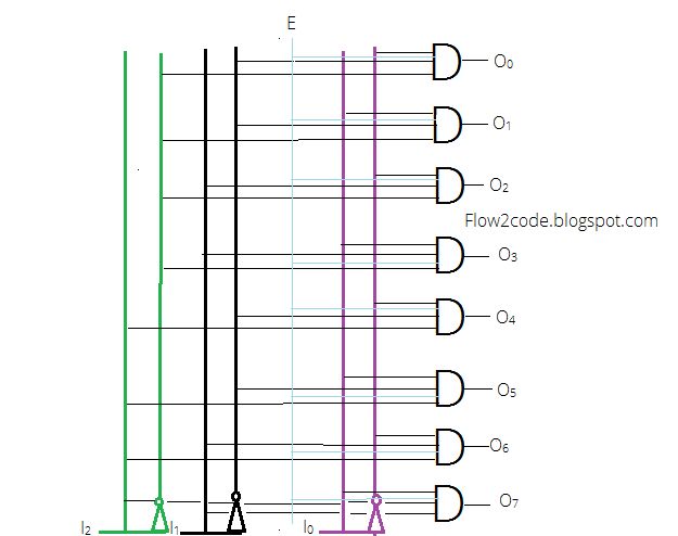
Step 3. With the help of the above expressions derived from the table, the circuit of a 3 to 8 decoder can be implemented.
Decoder Without E

Explanation:
In the above diagram, there were three input lines with their respective complements using Inverters. Each and every AND gate were holding three inputs from I1, I1 and I0 and producing 8 outputs.
Decoder with E
Explanation:
In above diagram, there were three input lines along with their complements using Inverters. Each and every AND gate were holding four inputs from E, I1, I1 and I0 and producing 8 outputs.