These are the following steps to design a 4 bit synchronous up counter using T flip flop:
Step 1: To design a synchronous up counter, first we need to know what number of flip flops are required. we can find out by considering a number of bits mentioned in the question. So, in this, we required to make 4 bit counter so the number of flip flops required is 4 [2n where n is a number of bits].
Step 2: After that, we need to construct a state table with excitation table.
Note: To construct excitation table from state table you should know the excitation table of respective flip flop, in this case, it is T flip flop. So check the excitation table for T flip flop Which is:
T Flip Flop Excitation Table
| Present state | Next State | T |
|---|---|---|
| 0 | 0 | 0 |
| 0 | 1 | 1 |
| 1 | 0 | 1 |
| 1 | 1 | 0 |
So, the above table is the excitation table for T Flip Flop.
State Table with excitation table
| Present State | Next State | Flip Flop | |||||||||
| Q4 | Q3 | Q2 | Q1 | Q'4 | Q'3 | Q'2 | Q'1 | T4 | T3 | T2 | T1 |
| 0 | 0 | 0 | 0 | 0 | 0 | 0 | 1 | 0 | 0 | 0 | 1 |
| 0 | 0 | 0 | 1 | 0 | 0 | 1 | 0 | 0 | 0 | 1 | 1 |
| 0 | 0 | 1 | 0 | 0 | 0 | 1 | 1 | 0 | 0 | 0 | 1 |
| 0 | 0 | 1 | 1 | 0 | 1 | 0 | 0 | 0 | 1 | 1 | 1 |
| 0 | 1 | 0 | 0 | 0 | 1 | 0 | 1 | 0 | 0 | 0 | 1 |
| 0 | 1 | 0 | 1 | 0 | 1 | 1 | 0 | 0 | 0 | 1 | 1 |
| 0 | 1 | 1 | 0 | 0 | 1 | 1 | 1 | 0 | 0 | 0 | 1 |
| 0 | 1 | 1 | 1 | 1 | 0 | 0 | 0 | 1 | 1 | 1 | 1 |
| 1 | 0 | 0 | 0 | 1 | 0 | 0 | 1 | 0 | 0 | 0 | 1 |
| 1 | 0 | 0 | 1 | 1 | 0 | 1 | 0 | 0 | 0 | 1 | 1 |
| 1 | 0 | 1 | 0 | 1 | 0 | 1 | 1 | 0 | 0 | 0 | 1 |
| 1 | 0 | 1 | 1 | 1 | 1 | 0 | 0 | 0 | 1 | 1 | 1 |
| 1 | 1 | 0 | 0 | 1 | 1 | 0 | 1 | 0 | 0 | 0 | 1 |
| 1 | 1 | 0 | 1 | 1 | 1 | 1 | 0 | 0 | 0 | 1 | 1 |
| 1 | 1 | 1 | 0 | 1 | 1 | 1 | 1 | 0 | 0 | 0 | 1 |
| 1 | 1 | 1 | 1 | 0 | 0 | 0 | 0 | 1 | 1 | 1 | 1 |
Above table is created as per follow :
When Q4 =0 which is present state and Q4‘=0 which is next state then T4 become 0 [As per excitation table, have a look ]
Similarly, if Q4 is 0 and Q4‘ is 1 then T3 become 1.
In similar way it goes on .
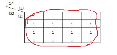
Step 3: After making the excitation table the next thing to do is dig out the equation from the boolean algebra or K map for the design of the counter. So, for T1 , T2, T3 and T4 we got 1, Q1, Q1.Q2 and Q1.Q2.Q3
K-Map
For T4 Flip flop,
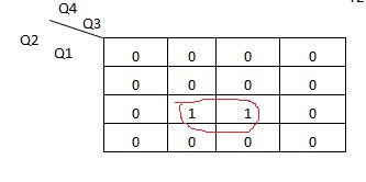
For T3 Flip flop,
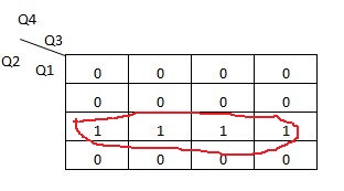
For T2 Flip flop,
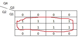
For T1 Flip flop,
Step 4: Lastly according to the equation got from K map create the design for 4 bit synchronous up counter.
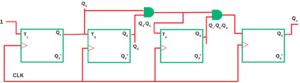
In above design T1 is getting input logic 1 and T2 is getting input from the output of the T1 flip flop and T3 is getting input from the output of T1 and T2 lastly, T4 is getting input from the output of T1 T2 and T3. A clock is attached to it which is in blue colour.
Related Posts:
Design a 3 bit synchronous up counter using T Flip flop?
Design a 2 bit Synchronous up counter using T Flip flop?