These are the following steps to Design a 3 bit synchronous up counter using T Flip flop:
Step 1: To design a synchronous up counter, first we need to know what number of flip flops are required. we can find out by considering a number of bits mentioned in the question. So, in this, we required to make 3 bit counter so the number of flip flops required is 3 [2n where n is a number of bits].
Step 2: After that, we need to construct state table with excitation table.
Note: To construct excitation table from state table you should know the excitation table of respective flip flop, in this case, it is T flip flop. So check the excitation table for T flip flop Which is:
T Flip Flop Excitation Table
| Present state | Next State | T |
|---|---|---|
| 0 | 0 | 0 |
| 0 | 1 | 1 |
| 1 | 0 | 1 |
| 1 | 1 | 0 |
So, the above table is the excitation table for T Flip Flop.
State Table with excitation table
| Present State | Next State | Flip Flop | ||||||
|---|---|---|---|---|---|---|---|---|
| Q3 | Q2 | Q1 | Q'3 | Q'2 | Q'1 | T3 | T2 | T1 |
| 0 | 0 | 0 | 0 | 0 | 1 | 0 | 0 | 1 |
| 0 | 0 | 1 | 0 | 1 | 0 | 0 | 1 | 1 |
| 0 | 1 | 0 | 0 | 1 | 1 | 0 | 0 | 1 |
| 0 | 1 | 1 | 1 | 0 | 0 | 1 | 1 | 1 |
| 1 | 0 | 0 | 1 | 0 | 1 | 0 | 0 | 1 |
| 1 | 0 | 1 | 1 | 1 | 0 | 0 | 1 | 1 |
| 1 | 1 | 0 | 1 | 1 | 1 | 0 | 0 | 1 |
| 1 | 1 | 1 | 0 | 0 | 0 | 1 | 1 | 1 |
Above table is created as per follow :
When Q3 =0 which is present state and Q3‘=0 which is next state then T3 become 0 [As per excitation table, have a look ]
Similarly, if Q3 is 0 and Q3‘ is 1 then T3 become 1.
In similar way it goes on .
Step 3: After making the excitation table the next thing to do is dig out the equation from the boolean algebra or K map for the design of the counter. So, for T1 , T2 and T3 we got 1, Q1 and Q1.Q2
K-Map
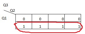
For T3 Flip flop,
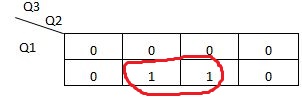
For T2 Flip flop,
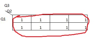
For T1 Flip flop,
Step 4: Lastly according to the equation got from K map create the design for 3 bit synchronous up counter.

In above design, T1 is getting input 1 and T2 is getting input from the output of the T1 flip flop and lastly, T3 is getting input from the output of T1 and T2 . A clock is attached to it which is in blue colour.
Popular Posts: